VENTS KSD series

| VENTS KSD series |
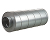
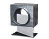
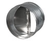
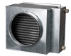
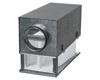
Inline centrifugal fans with forward curved in sound- and thermal insulated casing with air capacity up to 3930 m3/h for supply and exhaust ventilation systems installed in various premises with high demands to noise level. Fan models with two suction tubes are used to facilitate synchronous air extract from several areas or several premises. The fans are designed for connection to round air ducts.
| Series | Exhaust flange diameter [mm] | Intake flange diameter [mm] * | Number of intake flanges | Number of poles | Phase | Options | ||||||
|---|---|---|---|---|---|---|---|---|---|---|---|---|
|
VENTS KSD | 250; 315 | 250 | 2 | 4; 6 | E - single phase |
S - high-powered motor; R - power cord with IEC C14 electric plug; U – speed controller with electronic thermostat and temperature sensor integrated into the air duct. Equipped with power cord and IEC C14 electric plug. Temperature-based operation logic; Un – speed controller with electronic thermostat and external temperature sensor fixed on 4 m cable. Equipped with power cord and IEC C14 electric plug. Temperature-based operation logic; U1 – speed controller with electronic thermostat and temperature sensor integrated into the air duct. Equipped with power cord and IEC C14 electric plug. Timer-based operation logic; U1n – speed controller with electronic thermostat and external temperature sensor fixed on 4 m cable. Equipped with power cord and IEC C14 electric plug. Timer-based operation logic. |
* no intake flange diameter if it is equal to the exhaust flange diameter
Application
KSD fan is designed for use in supply and exhaust ventilation systems with high requirements to noise level.
Design
The fan casing is made of galvanized steel plate and heat-and sound-insulated material. The connecting flanges are fitted with rubber seals. The fan series KSD 315/250* 2 are equipped with two intake flanges Ø 250 mm to facilitate simultaneous air exhaust from several areas or rooms.
Motor
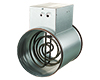
Four- or six-pole external rotor asynchronous motor equipped with double-inlet impeller with forward curved blades. The motor has overheating protection with automatic restart. Due to ball bearings with specially selected grease type the fan is maintenance-free and distinguished by low-noise operation.
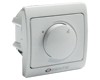
Speed control
Smooth or step speed control with a thyristor or autotransformer speed controller. Several fans may be connected to one speed controller provided that the total power and operating current do not exceed the rated speed controller parameters.
Mounting
The inline fans are designed for mounting with round air ducts.
In case of mounting with flexible connectors the fan is attached to a building with supports, suspension or fixing brackets. The fan is suitable for mounting in any position in compliance with the air motion direction in the system (shown with pointer on the fan casing). While mounting sufficient space for fan maintenance must be provided.
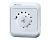
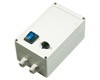
The fan with electronic temperature and control module (U option)
The ideal solution for ventilation of the premises requiring permanent temperature control, i.e. greenhouses. The fan with the electronic temperature and speed control module provides automatic control of the motor speed (air capacity) depending on air temperature in the air duct or in the room.
The front panel of the electronic module has the following control knobs:
- speed control knob for setting the motor speed;
- thermostat control knob for setting the temperature set point;
- thermostat indicator light.
The fan is available in two modifications:
- with the temperature sensor integrated inside the fan air duct (U/U1 option);
- with the external temperature sensor fixed on the cable, 4 m long (Un / U1n).
Control logic of the fan with the electronic temperature and speed control module
Set the desired air temperature (thermostat set point) by turning the thermostat control knob. Set the required minimum impeller speed (air flow) by turning the speed control knob. The motor switches to maximum speed (maximum air flow) as the temperature reaches and exceeds the set temperature set point. The motor switches to the preset lower speed as the temperature drops down below the temperature set point. To avoid frequent motor speed switches when the air temperature in the duct is equal to the set temperature point, the speed switch delay is activated. There are two switch delay patterns for various cases:
- The temperature sensor-based switch delay (U option): the motor switches to higher speed as the air temperature exceeds 2 °C above the set thermostat set point. The motor revers to the preset lower speed as the air temperature drops below the thermostat set point. This pattern is used to keep air temperature to within 2 °C. In this case the motor speed switches are rare.
- The timer-based switch delay (U1 option): as the air temperature exceeds the set thermostat set point, the motor switches to higher speed and the switch delay timer is activated for 5 min. The motor reverts to lower speed as the air temperature drops down below the thermostat set point and only after 5 minuts timer countdown. This pattern is used for exact air temperature control. The speed switches for the fan with U1 option are more frequent as compared to the operating logic of the fan with U option, however the minimum operating cycle at one speed is 5 minutes.
Example for temperature sensor delay: |
Example for timer delay: |
|
Initial conditions:
|
Initial conditions:
|
| Fan operates with the rated speed =60% | motor operates with the motor speed =60% |
|
↓
|
↓
|
|
|
| ↓ | ↓ |
|
fan switches to the maximum speed =100% and the delay timer switches for 5 minutes on |
| ↓ | ↓ |
|
|
| ↓ | ↓ |
|
|
| ↓ | |
|
after the timer stops, the motor switches to the preset rated speed (=60%). After the speed switch the timer switches again for 5 minutes on. | |
| ↓ | |
| |
| ↓ | |
|
after the timer stops, the motor switches to the maximum speed (=100%). After the speed switch the timer switches again for 5 minutes on. | |
|
Thus, in timer delay pattern the delay timer activates every time the fan |
SR series (round)
FB series (round)
KOM series
NKV series (round)
NK series (round)
Speed controller R-1/010
Speed controller RS-1-300
Single phase speed controller RSA5E-2-P
FBK series (round)
Thank your for your time and your wish to improve our site.