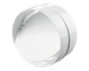
VENTS 100 LD
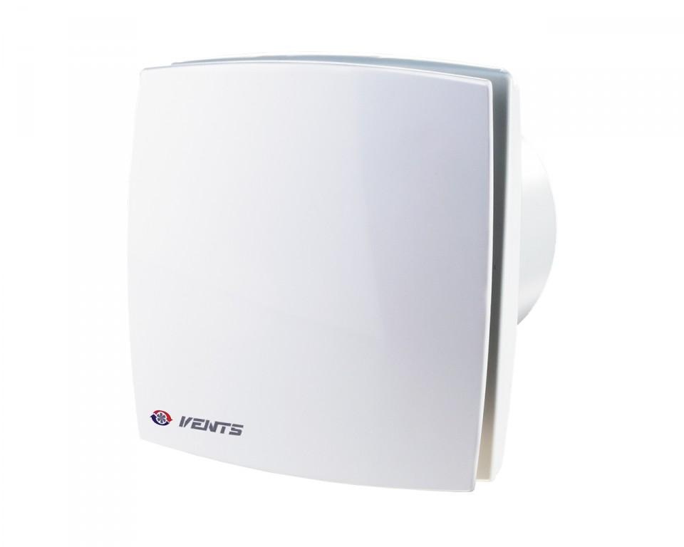
| VENTS 100 LD |


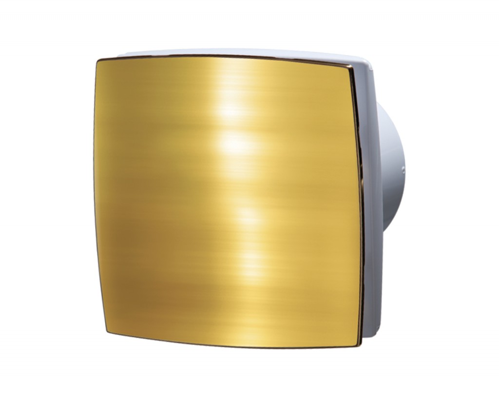
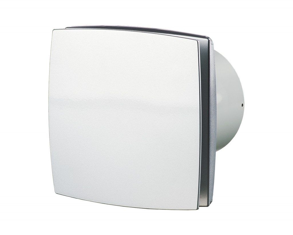
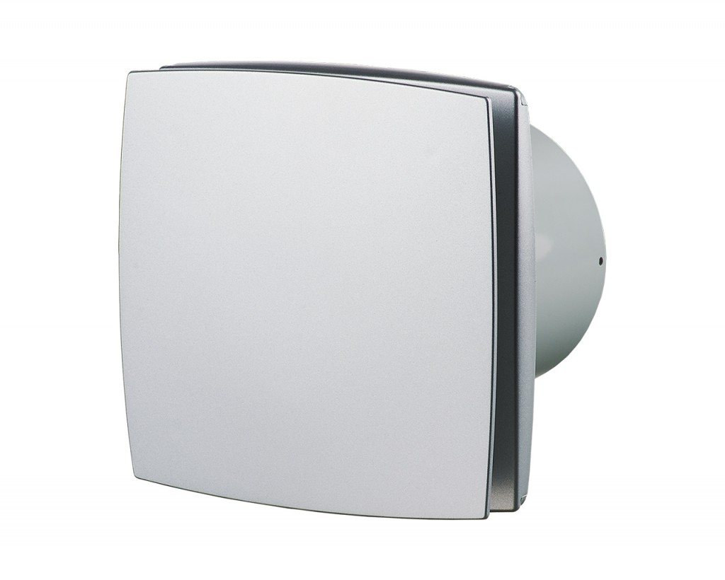
Maximum capacity - 88 m3/h.
|
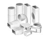
Ventilation ducts
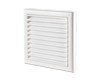
Supply and exhaust grilles and hoods
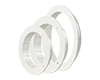
Back valve KO series
Window flange FO series
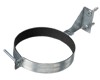
Clamps
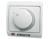
Electrical accessories
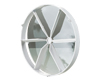
Connector with backdraft damper for round ducts
| Parameter | Value | Unit | |
|---|---|---|---|
220-240 | V | ||
50/60 | Hz | ||
14 | W | ||
88 51,832 24,464 0,02446 1469,6 | m³/h CFM l/s m³/s l/m | ||
0.085 | A | ||
2300 | min -1 | ||
33 | [dBA] | ||
0.6 | kg | ||
IP 34 | class | ||
100 | mm | ||
220-240V / 50-60Hz | |||
| Sizes | ∅D | B | H | L | L1 |
|---|---|---|---|---|---|
| mm | 100 | 152 | 120 | 126 | 30 |
| Wiring diagram for the fans equipped with a built-in switch | Wiring diagram for the fans without built-in switch |
 |
 |
| Wiring diagram for the fans equipped with a timer / timer, humidity sensor and a built-in switch | Wiring diagram for the fans equipped with a timer / timer with a humidity sensor without built-in switch |
 |
 |
| Wiring diagram for the fans with a light lamp. Separate activation of the fan and the built-in lamp. | Wiring diagram for the fans with a light lamp. Parallel activation of the fan and the built-in lamp. |
 |
 |
| Wiring diagram for the fans with an light lamp and grounding. Separate activation of the fan and the built-in lamp. | Wiring diagram for the fans with a light lamp and grounding. Parallel switching of the fan and the built-in lamp. |
 |
 |
| Wiring diagram for the fans with grounding | |
 |
* - only for fans designed for 12 V rated voltage (specified on the fan casing and packing).
S, S1, S2 - external switches.
Operating logic of the fans with optional equipment
- The fan equipped with a timer is activated by the control voltage supplied to LT input. After the control voltage is disconnected the fan continues operating within the time period within 2 to 30 minutes according to the timer settings. The turn-off delay time is adjusted by turning the respective potentiometer T control knob clockwise to increase and counter-clockwise to reduce it.
- The fan equipped with a timer and humidity sensor is activated by the control voltage supplied to LT input or in case of exceeding the preset humidity threshold value adjustable from ~60% to ~90%. After the control voltage is disconnected or as the humidity level H drops below the set threshold the fan continues operating within the time period within 2 to 30 minutes according to the timer settings. The turn-off delay time and the threshold humidity level are adjusted by turning the control knob of the respective potentiometer T for timer and H for humidity sensor clockwise to increase and counter-clockwise to reduce the set value. To set the maximum humidity level (90%) set the potentiometer control knob for H max position.
- The fan equipped with a timer and motion sensor is activated in case of the moving detection at the distance from 1 m to 4 m with 100° detection angle. After motion is off the fan continues operating within the time period within 2 to 30 minutes according to the timer settings. The turn-off delay time is adjusted by turning the respective potentiometer T control knob clockwise to increase and counter-clockwise to reduce it.
- Wiring diagram for connection of the light lamp to the fan timer operated by the common switch is shown on diagram 4. Upon the light lamp disconnection the fan continues operating according to the timer setting within the set time period.
Thank your for your time and your wish to improve our site.