VUT R 400 WH EC
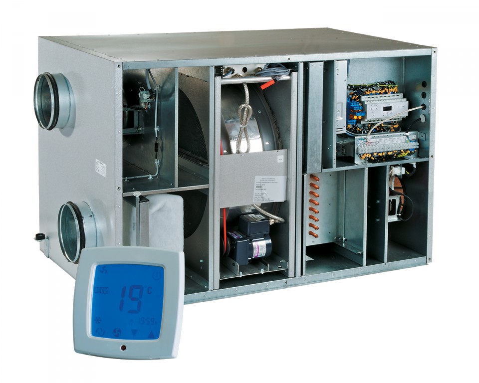
| VUT R 400 WH EC |
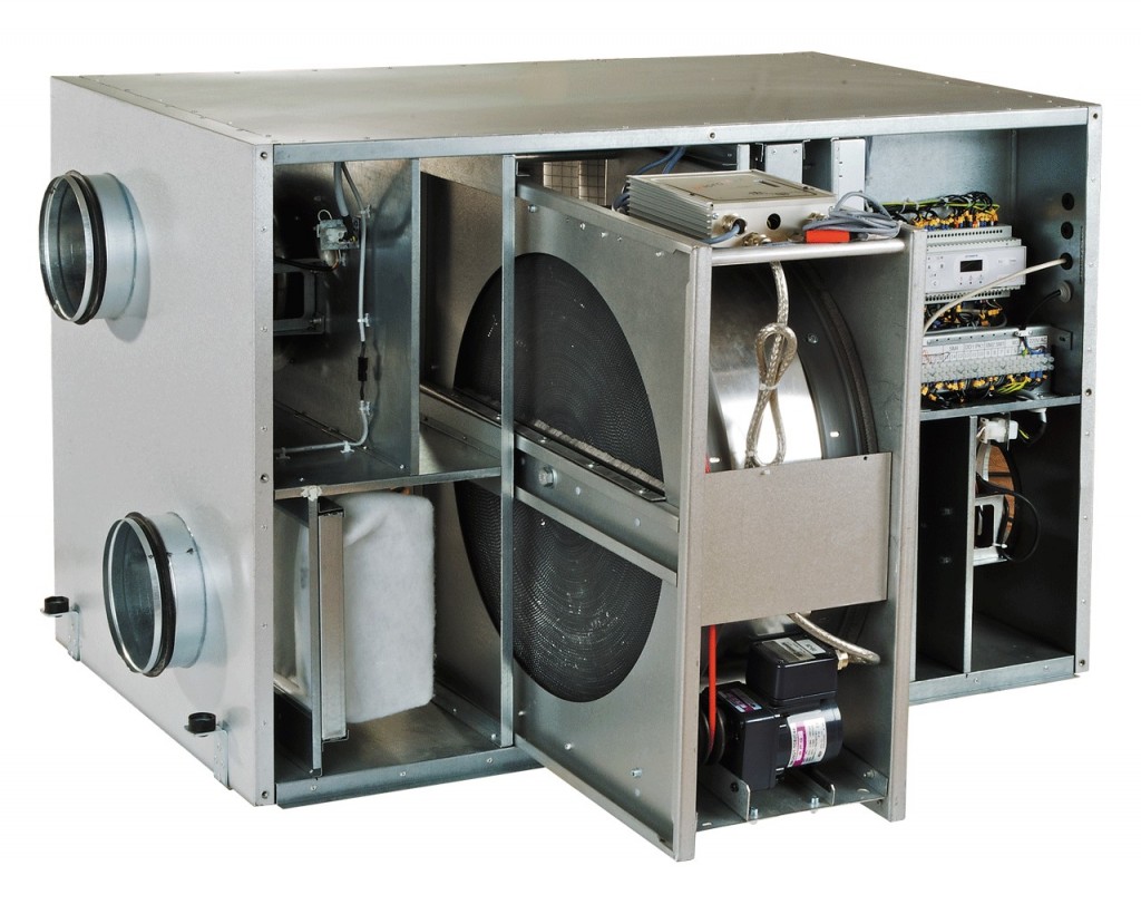
Air handling unit in sound- and heat-insulated casing with integrated water heater. Maximum capacity - 400 m3/h.
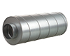
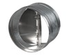
SR series (round)
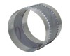
KOM series
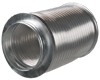
VVG series (round)
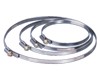
SRF series
C series
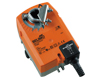
BELIMO TF230/TF24
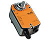
BELIMO LF230/LF24
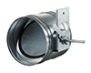
KRV series (round)
*option
| Parameter | Value | Unit | |
|---|---|---|---|
1 | ˜ | ||
220-240 | V | ||
50/60 | Hz | ||
2 pcs. x 100 | W | ||
290 | W | ||
1.2 | A | ||
400 235,6 111,2 0,1112 6680 | m³/h CFM l/s m³/s l/m | ||
3100 | min -1 | ||
45 | [dBA] | ||
aluzinc | |||
-25 +60 | оC | ||
20 mm, mineral wool | |||
160 | mm | ||
112 | kg | ||
G4 | |||
G4 (F7*) | |||
85 | up to % | ||
rotary | |||
aluminium | |||
yes | |||
air handling units with heat recovery | |||
yes | |||
A | |||
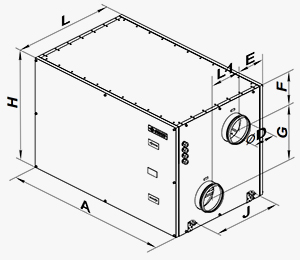
| Sizes | ∅D | A | E | F | G | J | H | L | L1 |
|---|---|---|---|---|---|---|---|---|---|
| mm | 159 | 1050 | 225 | 167 | 333 | 440 | 670 | 648 | 200 |
Thank your for your time and your wish to improve our site.