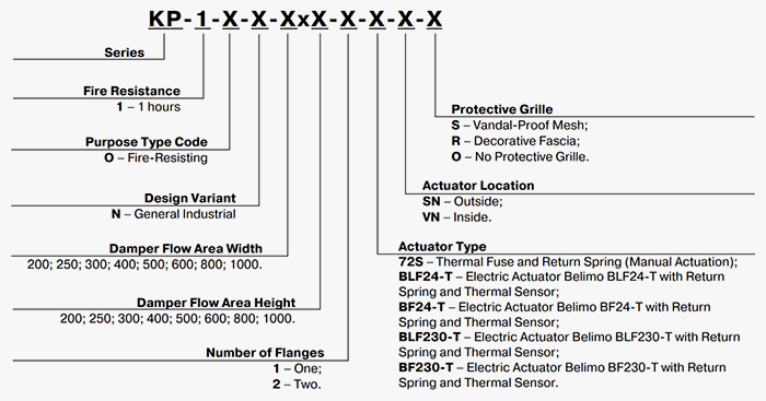
KP-1...72S series
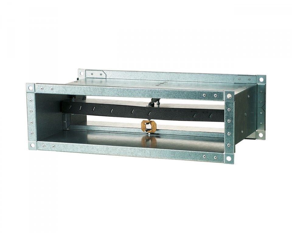
Normally open fire-resisting duct damper with mechanical drive mechanism.
Application
Fire dampers are intended for automatic blocking of process openings and the those of air duct ducts in intermediate floors, walls and partitions as well as blocking the openings in supply and exhaust ducts of smoke ventilation systems. The dampers of this particular design are not suitable for installation in air ducts and channels of premises rated explosion and fire safety category A and B and in flammable and explosive mixture intakes. KP-1 Fire-Resisting Duct Dampers are capable of resisting fire for at least 60 minutes (EI 60) at the temperature of 600 °С.
Design
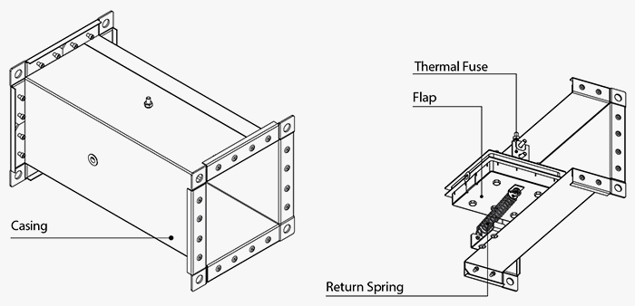
KP-1 series dampers are made in the generalpurpose industrial version with a minimized variety of hardware components using low-alloy galvanized steel. The damper flap is made of fire-resistant material. The duct installation design results in two mounting flanges on the casing for integration into a ventilation ducts (air ducting) and external configuration of the drive mechanism for easier maintenance. KP-1 series dampers are characterised by a simplified design and the absence of a hot and cold zone baffle. Depending on the design variant KP-1 series dampers are equipped with:
- a mechanical actuating unit with a thermal fuse and a return spring.
The damper is set to the operating position upon the thermal fuse breakdown resulting from a temperature increase.
Emergency Damper Actuation: The flap remains in the protective position (damper unaffected by fire) and is fixed by a thermal fuse (the return spring is cocked upon setting the damper to the protective position). Upon emergency actuation (damper directly affected by fire) the thermal fuse breaks down and the return spring sets the flap to the operating condition.
- Electric Actuator with Built-In Return Spring and Back-Up Thermal Breaker.
Damper Setting to Operating Position (Direct Fire Contact): Remotely, Via Electric Wire. The damper can be set to the operating or protective position either remotely via the control panel or manually using the manual cocking handle which is always included in the standard delivery package of the electric actuator.
In case of the remote control panel failure the backup thermal breaker interrupts the power supply to the electric actuator and the return spring sets the damper to the operating position.
Emergency Damper Actuation: The damper flap is automatically set to the protective position (damper unaffected by fire). The electric actuator remains energized at all times.
In case of an emergency actuation (direct fire contact): The electric actuator equipped with a return spring is de-energized and the damper flap is set to the operating position by means of the spring energy. In case of a power failure not related to fire and subsequent restoration to damper equipped with a return spring the damper flap is re-set to the protective position.
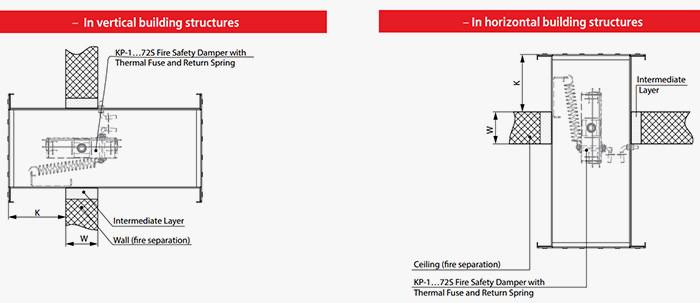
KP-1...72S Fire-Safety Damper with Mechanical Actuating Unit, Thermal Fuse and Return Spring
Installation
The damper must be installed into the building envelope structure in accordance with the applicable standards and regulations. The seal fire resistance must be at least equal to that of the building envelope.
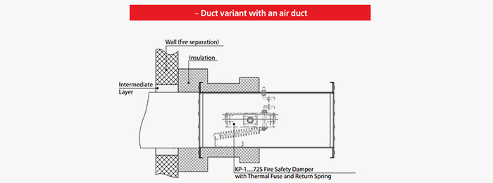
The dampers can be installed in any position in vertical and horizontal channels of fire-protection structures. The channels for damper installation must be made in such a way so as to prevent the transfer of loads caused by the fire-protection structures to the damper casing. The adjoining air duct must be suspended in such a way so as to prevent the transfer of air duct load to the damper flange. The minimum free space for accessing the control parts must be at least 350 mm. Make sure to arrange an inspection hole. While carrying out the installation mind size К. When two or more dampers are installed into the same fire-protection separation structure the distance between the two adjacent dampers must be at least 200 mm. The damper must be installed in such a way that the damper flap (in its closed position) lies in the fire-protection separation structure plane. If such installation is not possible, the damper casing part between the fire-protection separation structure and the damper flap must be insulated with a suitable material pursuant to the applicable standards.
The damper control mechanism must be protected against damage and contamination. The damper casing must not deform any deformation during embedding. After the installation the flap must not catch against the damper casing while opening or closing. The fire-safety damper can be integrated into a tight wall structure - e.g. made of conventional concrete work of minimum width W = 100 mm or into a plasterboard wall of the necessary fire resistance class or into a tight ceiling structure - e.g. made of conventional concrete of minimum width W = 150 mm. Do not use any foaming substances for sealing the damper in the separation structure.
Installation Recommendations for KP-1...72S Dampers with Thermal Fuse and Return Spring:

Extra Accessories
-
RD smoke exhaust grille
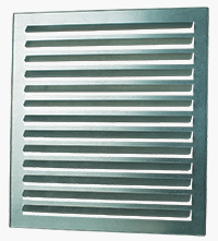
KP-1 Fire-Resisting Dampers can be additionally equipped with a smoke exhaust grille. The smoke exhaust grille is used to entirely block the external view of the damper internals in the absence of strict requirements to the unit appearance. The smoke exhaust grille also doubles as unauthorized access protection for the damper and its actuator. The grille has a single horizontal row of non-adjustable air flow guides fixed at 45 degrees. The grille can be made of galvanized steel (Zn), carbon steel with a special coating (M), stainless steel (N) or aluminium (A). The grille is attached directly to the damper flange by means of self-tapping screws with the flaps facing outward and does not require any additional recessing of the damper.
Thank your for your time and your wish to improve our site.