Login

Privacy Policy (GDPR)
Authorization
Not registered yet? Take advantages of registration:
Products saving in a binding to the projects
Product consultation from our experts - Online
Registration
Signup
By using this form, you confirm that you have read the site terms of use Terms of use and completely accept the terms of use

VENTS VK 250 Duo


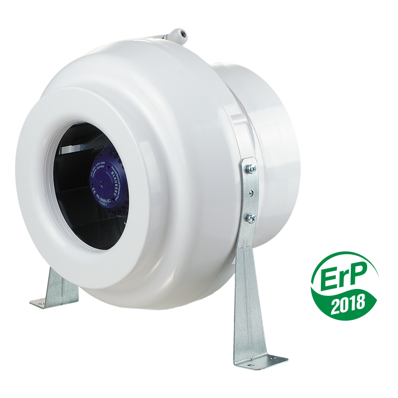
Inline centrifugal fan in plastic casing with the air flow up to 1126 m³/h.

  • Description
  • Characteristics
  • Capacity diagram
  • Downloads
  • Dimensions
  • Additional characteristics
  • Designation key
  • Video
  • BIM
Description
Description
APPLICATIONS
  • VK fans are applied for supply and exhaust ventilation systems of commercial, office and other premises.
  • Compatible with Ø 100, 125, 150, 200, 250 and 315 mm round air ducts.
  • Models marked VK...Q are supplied with quiet motors for low-noise applications. 
  • Due to the corrosion-resistant durable plastic casing, these models are the perfect solution for the installation in exhaust ventilation systems in humid premises such as bathrooms, kitchens etc.
DESIGN
  • The casing is made of high-quality durable plastic.
  • The fans are equipped with waterproof terminal boxes. 
  • Models marked VK..R are supplied with the power cord and a plug.
MOTOR
  • A centrifugal impeller with backward curved blades is powered by a single-phase external rotor motor.
  • The motor is equipped with self-resetting overheating protection.
  • Some standard sizes are available with a high-powered motor, see VKS modifications.
  • The motor is equipped with ball bearings for a long service life designed for at least 40 000 operating hours.
  • For precise features, safe operation and low noise, each impeller is dynamically balanced while assembly.
  • Motor protection rating is IP 44.
  • The double-speed models (Duo) are equipped with asynchronous electric external rotor motors and centrifugal impellers with forward curved blades. The impellers are dynamically balanced. Double-speed control. 
SPEED CONTROL
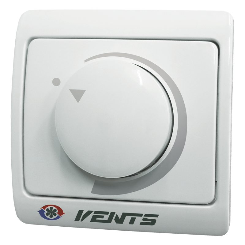
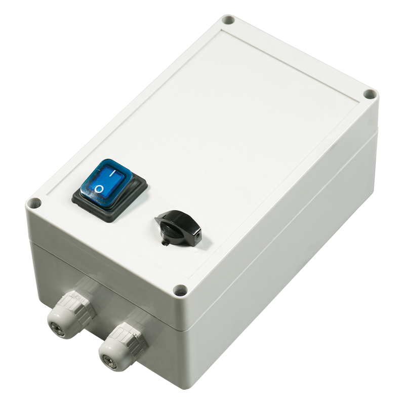
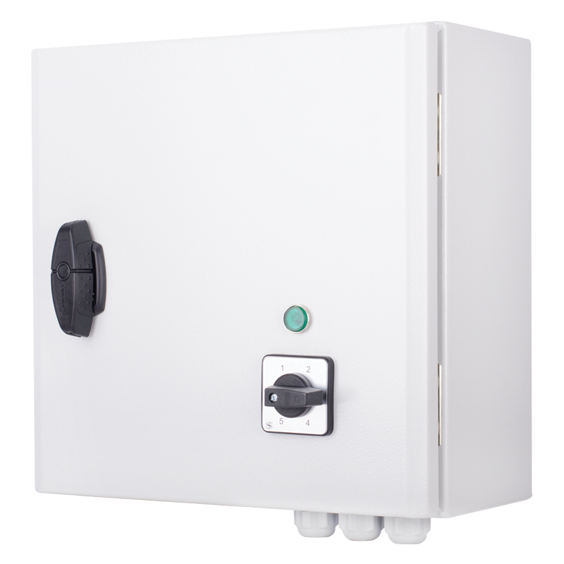
  • Smooth or step speed control with a thyristor or autotransformer speed controller.
  • Several fans may be connected to one speed controller provided that the total power and operating current do not exceed the rated speed controller parameters.
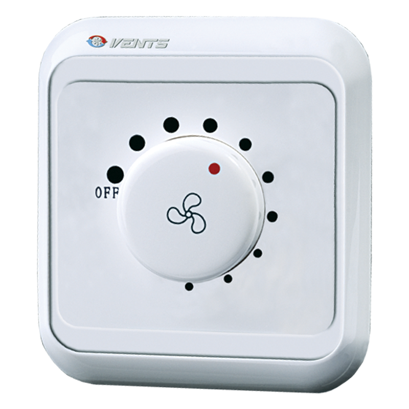
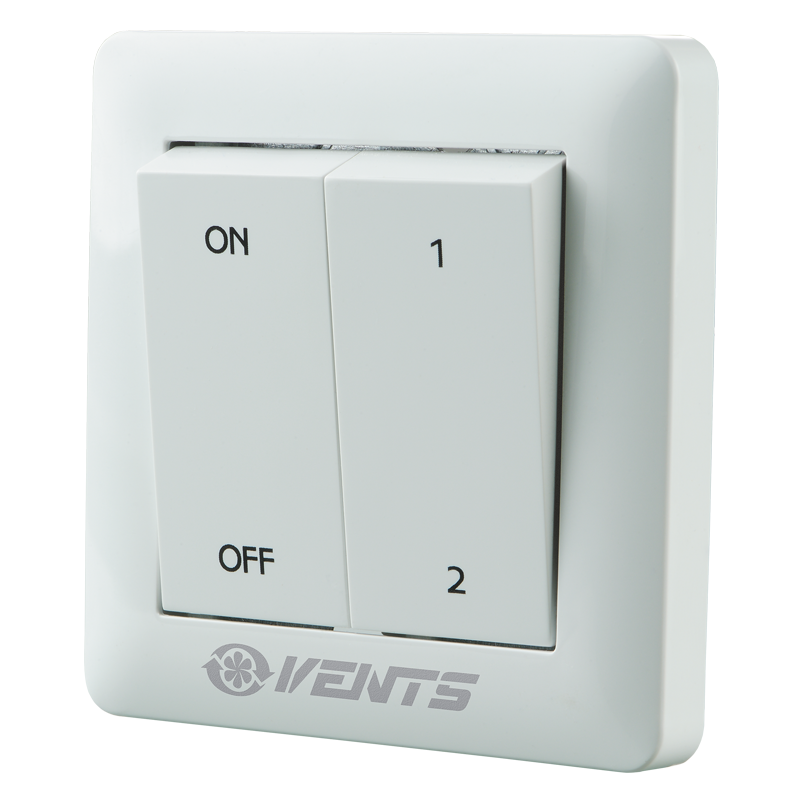
  • Two-speed models are controlled with the external speed switch P2-10 (available separately).
MOUNTING

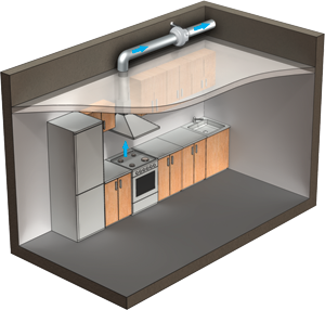
VK fan kitchen exhaust ventilation example

  • The fan is mounted to the wall or ceiling with mounting brackets included into delivery set or with PVK holders, specially ordered accessory.
  • The fan can be mounted at any angle.
  • Electric connection and installation shall be performed in compliance with the manual and the wiring diagram on the terminal box.
THE FAN WITH ELECTRONIC TEMPERATURE AND CONTROL MODULE (U OPTION).
  • The ideal solution for ventilation of the premises requiring permanent temperature control, i.e. greenhouses.
  • The fan with the electronic temperature and speed control module provides automatic control of the motor speed (air capacity) depending on air temperature in the air duct or in the room.
  • The front panel of the electronic module has the following control knobs:
    • speed control knob for setting the motor speed;
    • thermostat control knob for setting the temperature set point;
    • thermostat indicator light.
  • The fan is available in two modifications:
    • with the temperature sensor integrated inside the fan air duct (U/U1 option);
    • with the external temperature sensor fixed on the cable, 4 m long (Un/U1n).
CONTROL LOGIC OF THE FAN WITH THE ELECTRONIC TEMPERATURE AND SPEED CONTROL MODULE
  • Set the desired air temperature (thermostat set point) by turning the thermostat control knob.
  • Set the required minimum impeller speed (air flow) by turning the speed control knob.
  • The motor switches to maximum speed (maximum air flow) as the temperature reaches and exceeds the set temperature set point. 
  • The motor switches to the pre-set lower speed as the temperature drops down below the temperature set point.
  • To avoid frequent motor speed switches when the air temperature in the duct is equal to the set temperature point, the speed switch delay is activated.
There are two switch delay patterns for various cases:
  • The temperature sensor-based switch delay (U option): the motor switches to higher speed as the air temperature exceeds 2 °C above the set thermostat set point. The motor revers to the preset lower speed as the air temperature drops below the thermostat set point. This pattern is used to keep air temperature to within 2 °C. In this case the motor speed switches are rare.
  • The timer-based switch delay (U1 option): as the air temperature exceeds the set thermostat set point, the motor switches to higher speed and the switch delay timer is activated for 5 min. The motor reverts to lower speed as the air temperature drops down below the thermostat set point and only after 5 minutes timer countdown. This pattern is used for exact air temperature control. The speed switches for the fan with U1 option are more frequent as compared to the operating logic of the fan with U option, however the minimum operating cycle at one speed is 5 minutes.
Example for temperature sensor delay pattern: Example for timer delay pattern:
  • Initial conditions:
    • rated speed is set as 60% of the maximum speed
    • operating threshold is set as 25 °С
    • air temperature in the duct is 20 °С
  • Initial conditions:
    • rated speed is set as 60% of maximum speed
    • operating threshold is set as 25 °С
    • air temperature in the duct is 20 °С
  • Motor operates with the rated speed =60%
  • Motor operates with the rated speed =60%
  • air temperature in the duct rises
  • Motor operates with the rated speed =60%
  • the temperature in the duct rises, reaches 25 °C and keeps rising
  • air temperature in the duct reaches 27 °С
  • Motor switches to the speed =100%
  • fan switches to the maximum speed =100% and the delay timer switches for 5 minutes again on
  • air temperature in the duct goes down
  • Motor operates with the speed =100%
  • the temperature in the duct goes down
  • the motor operates with the maximum speed =100%
  • temperature in the duct reaches 25 °C again
  • Motor switches to the preset rated speed =60%
  • the temperature in the duct reaches 25 °C and keeps rising
 
 
  • after the timer stops, the motor switches to the preset rated speed (=60%). After the speed switch the timer switches again for 5 minutes on.
 
 
  • the temperature in the duct rises, reaches 25 °C and keeps rising
 
 
  • after the timer stops, the motor switches to the maximum speed (=100%). After the speed switch the timer switches again for 5 minutes on.
 
  • Thus, in timer delay pattern the delay timer activates every time the fan speed changes.
Characteristics
Characteristics
Parameter VK 250 Duo
Min. speed
VK 250 Duo
Max. speed
Measurement unit
Phase 1 1 ˜
Voltage 230 230 V
Power consumption 147 176 W
Frequency 50 50 Hz
Current 0.66 0.76 A
Sound pressure level at 3 m distance 46 46 dBА
Maximum air capacity 642 1126 m³/h
RPM 1940 2370 min-1
Protection rating IP X4 IP X4 -
Duct diameter 250 250 mm
EC motor no no -
Design centrifugal centrifugal -
Casing material plastic plastic -
Width 354 354 mm
Weight 4.3 4.3 kg
Height 340 340 mm
SEC Class C C -
Outdoor mounting no no -
Sound-insulated casing no no -
Duct for round air ducts for round air ducts -
Type exhaust, supply exhaust, supply -
Mounting Inline Inline -
Capacity diagram
Capacity diagram
  • Selection method:
  • Air flow:
  • Pressure:
Operating point
  • Air flow: --
  • Pressure: ---
Files archieve
Downloads
Select document type
  • Advertising and printing products
  • Certificates
  • Technical documentation
Name
Certificate GS "VK" (pdf 128.5Kb)
Certificate LVD "VK" (pdf 99.77Kb)
"VENTS VK" user's manual 04-2022 (V02EN-14) (pdf 1.08Mb)
"VENTS VK, VENTS VK Duo" product description 05-2023 (pdf 2.29Mb)
Download high quality image "VENTS VK 100 (ErP 2016, 2018)" (psd 4.07Mb)
Declaration of сonformity "VK" (pdf 1.66Mb)
Declaration of сonformity "VK,VKM,VKMz" (pdf 1.64Mb)
Download image "VENTS VK 100 (ErP 2016, 2018)" for your website (png 314.36Kb)
Download high quality image "VENTS VK 125 (ErP 2016, 2018)" (psd 4.06Mb)
Download image "VENTS VK 125 (ErP 2016, 2018)" for your website (png 318.69Kb)
Download high quality image "VENTS VK 150 (ErP 2016, 2018)" (psd 4.19Mb)
Download image "VENTS VK 150 (ErP 2016, 2018)" for your website (png 360.3Kb)
Download high quality image "VENTS VK 200 (ErP 2016, 2018)" (psd 4.42Mb)
Download image "VENTS VK 200 (ErP 2016, 2018)" for your website (png 423.82Kb)
Download high quality image "VENTS VK 250 (ErP 2016, 2018)" (psd 4.31Mb)
Download image "VENTS VK 250 (ErP 2016, 2018)" for your website (png 384.4Kb)
Download high quality image "VENTS VK 315, VENTS VK 315 Duo (ErP 2016)" (psd 4.2Mb)
Download image "VENTS VK 315, VENTS VK 315 Duo (ErP 2016)" for your website (png 351.81Kb)
Download high quality image "VENTS VK 100 Duo (ErP 2018)" (psd 4.05Mb)
Download high quality image "VENTS VK 125 Duo (ErP 2018)" (psd 4.05Mb)
Download high quality image "VENTS VK 150 Duo (ErP 2018)" (psd 4.17Mb)
Download high quality image "VENTS VK 200 Duo (ErP 2018)" (psd 4.4Mb)
Download high quality image "VENTS VK 250 Duo (ErP 2018)" (psd 4.3Mb)
Download image "VENTS VK 100 Duo (ErP 2018)" for your website (png 300.4Kb)
Download image "VENTS VK 125 Duo (ErP 2018)" for your website (png 304.58Kb)
Download image "VENTS VK 150 Duo (ErP 2018)" for your website (png 346.9Kb)
Download image "VENTS VK 200 Duo (ErP 2018)" for your website (png 409.08Kb)
Download image "VENTS VK 250 Duo (ErP 2018)" for your website (png 369.16Kb)
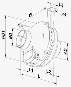
Dimensions
Characteristics
VENTS VK 250 Duo
Parameter Value Measurement unit
∅D 250 mm
ØD1 340 mm
B 354 mm
L 265 mm
L1 30 mm
L2 30 mm
L3 40 mm
Additional characteristics
A-weighted sound pressure level Octave-frequency band [Hz] Sound pressure level @ 3 m, A-filter applied Sound pressure level @ 1 m, A-filter applied
Hz         Gen. 63 125 250 500 1000 2000 4000 8000 LpA, 3 m [dBA] LpA, 1 m [dBA]
LwA to inlet dBA 86 51 73 71 75 81 82 77 67 66 76
LwA to outlet dBA 87 54 66 76 73 81 83 77 69 66 76
LwA to environment dBA 67 35 49 59 62 61 60 55 41 46 56
Designation key
Designation key
Series Duct diameter [mm] Options
VENTS VK S: high-powered motor 100; 125; 150*;
200; 250; 315
Duo: double-speed motor.
Q: low-powered motor.
U: speed controller with electronic thermostat and temperature sensor integrated into the air duct. Temperature-based operation logic.
Un: speed controller with electronic thermostat and external temperature sensor fixed on 4 m cable. Temperature-based operation logic.
U1: speed controller with electronic thermostat and temperature sensor integrated into the air duct. Timer-based operation logic.
U1n: speed controller with electronic thermostat and external temperature sensor fixed on 4 m cable. Timer-based operation logic.
U2n: speed controller with an electronic thermostat and a temperature sensor fixed on a 4 m cable. Temperature-based switching on/off.
V: speed switch (for Duo models).
R1: power cord with mains plug.
P: built-in smooth speed controller.

* VK 150 model is compatible with the air ducts both Ø 150 and 160 mm

Video
Video

BIM
BIM

Share your opinion

Questionnaire
Is our site helpful for your business development?