Login

Privacy Policy (GDPR)
Authorization
Not registered yet? Take advantages of registration:
Products saving in a binding to the projects
Product consultation from our experts - Online
Registration
Signup
By using this form, you confirm that you have read the site terms of use Terms of use and completely accept the terms of use

VENTS VUT 1000 PW EC

  • Description
  • Characteristics
  • Downloads
  • Dimensions
  • Additional diagrams
  • Legend
  • Accessories
Description
Description
DESCRIPTION
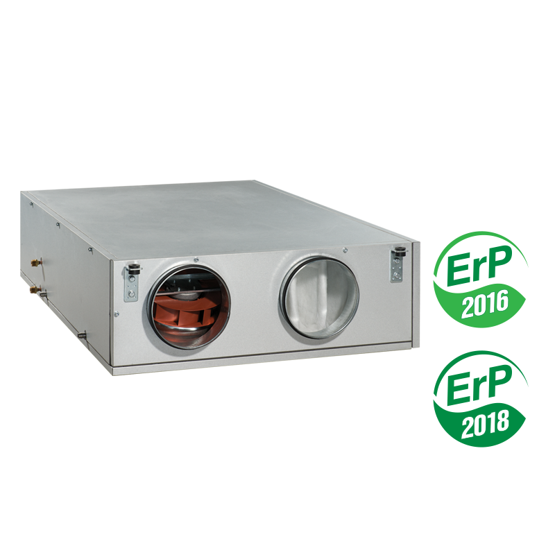
  • The VUT PW EC air handling units with water heater are the fully-featured ventilation units ensure air filtration, fresh air supply and stale air extract.

  • The heat energy contained in extract air is transferred to supply air through the plate heat exchanger.

  • The units are suitable for integration into various ventilation and air conditioning networks requiring cost-effective solutions and controllable ventilation.

  • The integrated EC motors reduce energy demand by half up to three-fold and provide high air flow and low noise level.

  • All the models are compatible with round 160 (150), 200, 250, 315 and 400 mm air ducts.

MODIFICATIONS CASING
  • VUT PW EC – models with water heater.

  • The aluzinc casing is internally filled with 20 mm mineral wool for VUT 600, 1000 PW EC and 25 mm for VUT 2000, 3000 PW EC units.

FILTER  
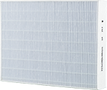
  • Supply and extract air flows are purified through two panel filters with filtering class G4. 

  • Supply filter F7 can be supplied with the few models.
MOTOR  
  • High-efficient electronically-commutated motors with external motor and impellers with backward curved blades.

  • Such motors are the most state-of-the-art energy-saving solution.

  • EC motors are featured with high performance and total speed controllable range.

  • High efficiency reaching 90% is the premium advantage of the electronically-commutated motors.

HEAT EXCHANGER  
  • VUT 600 and 1000 PW EC models are fitted with a counter-flow heat exchanger made of aluminum. VUT 2000 and 3000 PW EC models are fitted with a cross-flow plate heat exchanger made of aluminum.

  • All the units are equipped with a drain pan for condensate drainage.

HEATER CONTROL AND AUTOMATION
  • The water heater (for the unit VUT PW) the heat exchanger is designed for warming up of supply air up to the set level if heat recovery is not enough to attain the set supply air temperature.

  • The water heaters are designed for max. operating pressure 1.0 MPa (10 bar) and max. heat medium operating temperature +95 °C.
  • The unit includes an integrated automation and a multifunctional control panel with a remote LCD control panel.
  • The delivery set includes a 10 m connecting cable for connection of the unit to the control panel.
  • The freezing protection function is performed by means of the bypass and the heater.
  • In case of a freezing danger according to the temperature sensor readings the bypass damper is opened to let supply air flow through the bypass duct and not come in contact with the heat exchanger.
  • The heater warms up supply air up to the required temperature and meanwhile the heat exchanger is heated by the warm extract air.
  • After the heat exchanger defrosting the bypass damper closes the bypass duct and the air handling unit reverts to the standard operation mode.

The VUT PW EC unit incorporates a LCD control panel

with a colour sensor display PU SENS 01.

VUT PW EC CONTROL AND PROTECTION FUNCTIONS  

Control panel:

  • Turning air handling unit on/off, room temperature indication, low-medium-high speed selection.
  • Setting week-scheduled operation.
  • Supply and exhaust fan speed stage adjustment from 0 up to 100% during the system set-up.
  • Maintaining set supply air temperature by means of controlling the circulating pump and heat medium regulating valve of the water mixing unit.
  • Heater freezing protection according to the feedback of the temperature sensor at outlet of the heater and of the return heat medium temperature sensor.
  • Safe fan start/shutdown.
  • Return heat medium temperature maintenance during the fan standby;
  • Actuating external air dampers.
  • Maintaining set indoor or room air temperature.
  • Control according to the duct humidity sensor feedback HV1 (special accessory) or according to the humidity sensor in the control panel.
  • Filter clogging control by filter timer.
  • Ventilation system shutdown on signal from the fire alarm system.
  • Cooler connection possibility.
MOUNTING
 
  • The unit is designed for indoor mounting. While mounting the unit ensure its correct position to enable condensate collection and drainage.

  • Access for servicing and cleaning of the filter is from the right or left side panel for the dimension types 350, 600 and 1000 and from the bottom for the dimension types 2000 and 3000.
ACCESSORIES  
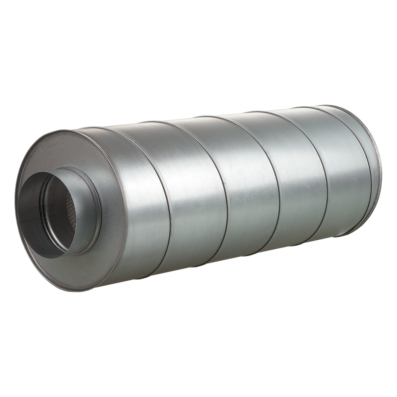
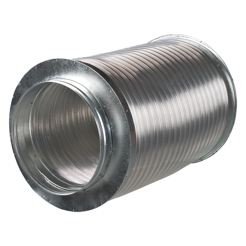
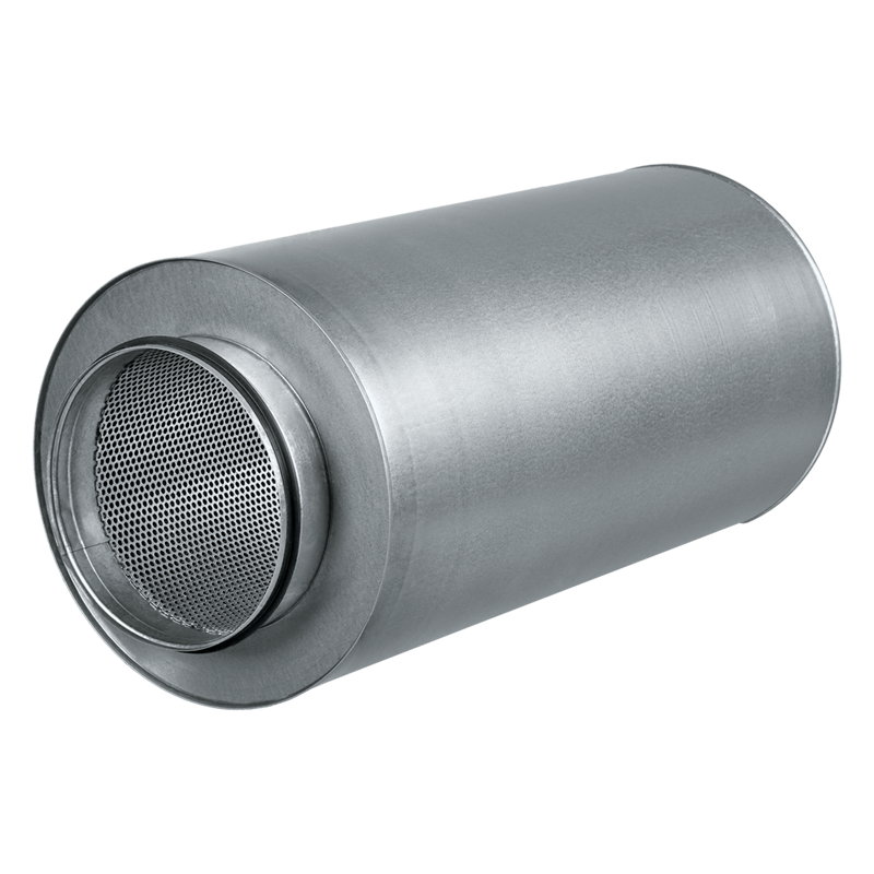
  • For attenuation of sound generated by the fans it is recommended to install the duct silencer (refer SR) from inside before the unit.

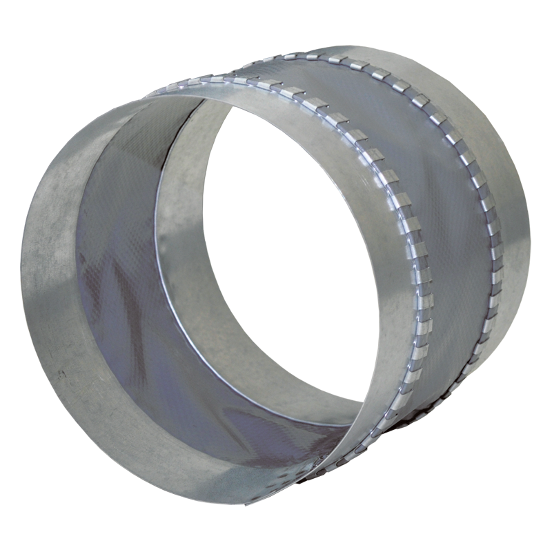
  • For absorbing of vibration in the air duct it is recommended to install the flexible anti-vibration connectors (refer VVG) on both sides of the unit.

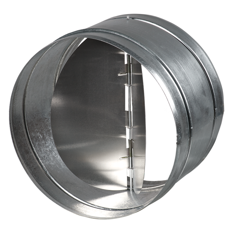
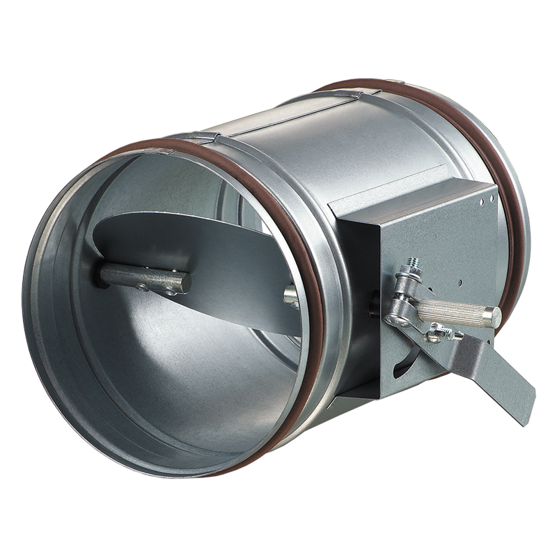
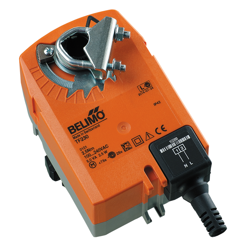
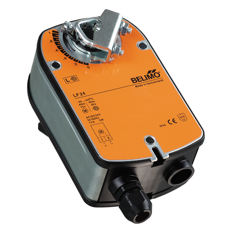
  • To disable uncontrollable air backdrafting during the fan standby and to prevent the water heater freezing the units must be equipped with automatic air dampers.
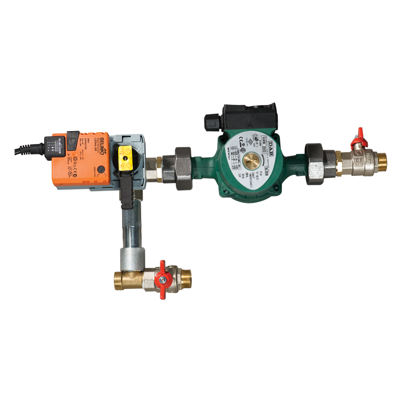
  • The mixing units USWK are recommended for smooth supply air temperature control in the units with water heaters.
  • The mixing unit USWK with three-way heat medium regulating valve and circulation pump provides smooth heating capacity regulation and minimizes freezing danger of the water heater.
Characteristics
Characteristics
Parameter VUT 1000 PW EC
Measurement unit
Phase 1 ˜
Voltage 230 V
Fan current 2,26 A
Maximum fan power 400 W
Frequency 50/60 Hz
Total unit power 400 W
Total unit current 2.26 A
Maximum air capacity 1000 m³/h
RPM 2780 min-1
Sound pressure level at 3 m distance 52 dBА
Transported air temperature -25 up to +40 °С
Casing material aluzinc -
Insulation 20 mm mineral wool -
Filter: extract G4 -
Filter: supply G4 (F7*) -
Connected air duct size 250 mm
Number of water (glycol) coil rows 4 -
Weight 98 kg
Heat recovery efficiency up to 90 %
Heat exchanger type counter-flow -
Heat exchanger material aluminium -
Files archieve
Downloads
Select document type
  • Advertising and printing products
  • Certificates
  • Technical documentation
Name
Download high quality image "VENTS VUT 600, 1000 PW EC (ErP 2016, 2018)" (psd 3.64Mb)
"VENTS VUT PE EC, VUT PW EC" product description 01-2019 (pdf 4.44Mb)
"VENTS VUT 600-1000 PW EC" user's manual 09-2019 (V49EN-09) (pdf 3.28Mb)
"VENTS VUT 2000-3000 PW EC" user's manual 05-2019 (V49-1EN-07) (pdf 5.72Mb)
"Control system for air supply and air handling units based on Freemax controllers and AC208A2 sensor control panels" user's manual 07-2023 (V99EN-03) (pdf 7.14Mb)
"LCD Control Panel PU JK 01" user's manual 11-2020 (V55-5EN-03) (pdf 4.85Mb)
"Sensor control panel PU SENS 01 A11/A19" user's manual 04-2019 (V55-6EN-11) (pdf 2.39Mb)
Download image "VENTS VUT 600, 1000 PW EC (ErP 2016, 2018)" for your website (png 247.05Kb)
Download high quality image "VENTS VUT 2000, 3000 PW EC (ErP 2016)" (psd 3.97Mb)
Download image "VENTS VUT 2000, 3000 PW EC (ErP 2016)" for your website (png 320.86Kb)
Dimensions
Characteristics
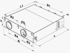
VENTS  VUT 1000 PW EC
Parameter Value Measurement unit
∅D 250 mm
B 1351 mm
B1 1216 mm
B2 608 mm
B3 431 mm
B4 655 mm
H 318 mm
H1 143 mm
L 1349 mm
L1 1402 mm
Additional diagrams
Additional diagrams
Sound-power level Octave-frequency band [Hz]
  Hz General 63 125 250 500 1000 2000 4000 8000
LWA to inlet dBA 67 68 67 67 66 59 61 61 56
LWA to outlet dBA 69 70 71 68 66 66 64 59 58
LWA to environment dBA 47 58 52 47 53 40 41 35 35


Legend
Legend
Series Rated air flow, [m3/h] Mounting modification Heater type Motor type Service side Control
VENTS VUT 350; 600; 1000; 2000; 3000 P: suspended W: water ЕС:synchronous electronically commutated motor
L: left
R: right
: PU SENS 01 control panel
Accessories
Accessories
Model G4 pocket filter F7 pocket filter G4 panel filter Outdoor humidity sensor Silencer Backdraft damper Air damper Clamps Electric actuators Mixing unit
   
VUT 600 PW ЕC SFK 392х236х27 G4 SFK 392х236х27 F7 >SF 782х128х20 G4   SR 200 600/900/1200 SRF 200 600/900/1200 КОМ 200 KRV 200 С 200 LF 230 TF 230 USWK
VUT 1000 PW ЕC SFK 647х274х27 G4 SFK 647х274х27 F7 SF 647х274х20 G4   SR 250 600/900/1200 SRF 250 600/900/1200 КОМ 250 KRV 250 С 250 LF 230 TF 230 USWK
VUT 2000 PW ЕC - - SF 708х480х48 G4   SR 315 600/900/1200 SRF 315 600/900/1200 КОМ 315 KRV 315 С 315 LF 230 TF 230 USWK
VUT 3000 PW ЕC - - SF 827х741х48 G4   SR 400 600/900/1200 SRF 400 600/900/1200 КОМ 400 KRV 400 С 400 LF 230 TF 230 USWK
Share your opinion

Questionnaire
How often do you use equipment selection program?