Domestic fans
  Industrial and commercial fans
  Single-room ventilation systems with heat recovery
  Air handling units
  Air heating systems
  Smoke extraction and ventilation
  Air sterilizers
  Accessories for ventilating systems
  Electrical accessories
  Ventilation ducts and fittings
  Air distribution components
  Ventilation kits and vents
 Centrifugal fan VENTS VNV-1 80 KP
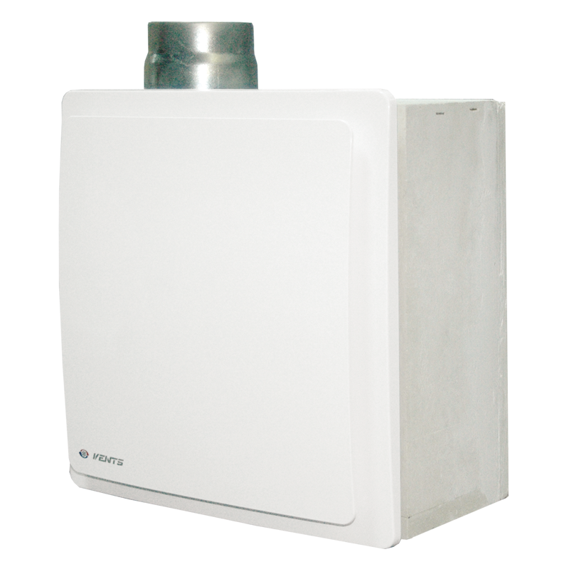

Centrifugal fan in fireproof casing with air capacity up to 100 m3/h.


- Description
- Modifications
- Capacity diagram
- Downloads
- Certificates
- Options description
- BIM
| APPLICATIONS | |
|
|
| DESIGN | |
|
|
| MOTOR | |
|
|
| MODIFICATIONS AND OPTIONS | |
|
VNV-1A(E) 80 KP T — the fan is equipped with a timer. |
VNV-1A(E) 80 KP I — the fan is equipped with an interval switch. |
|
|
| VNV-1A(E) 80 KP-P — the fan is equipped with a front panel from mirror finish aluminium. VNV-1A(E) 80 KP-L — the fan is equipped with a extra branch pipe on the left. |
VNV-1A(E) 80 KP-D — the fan is equipped with a extra branch pipe on the bottom. |
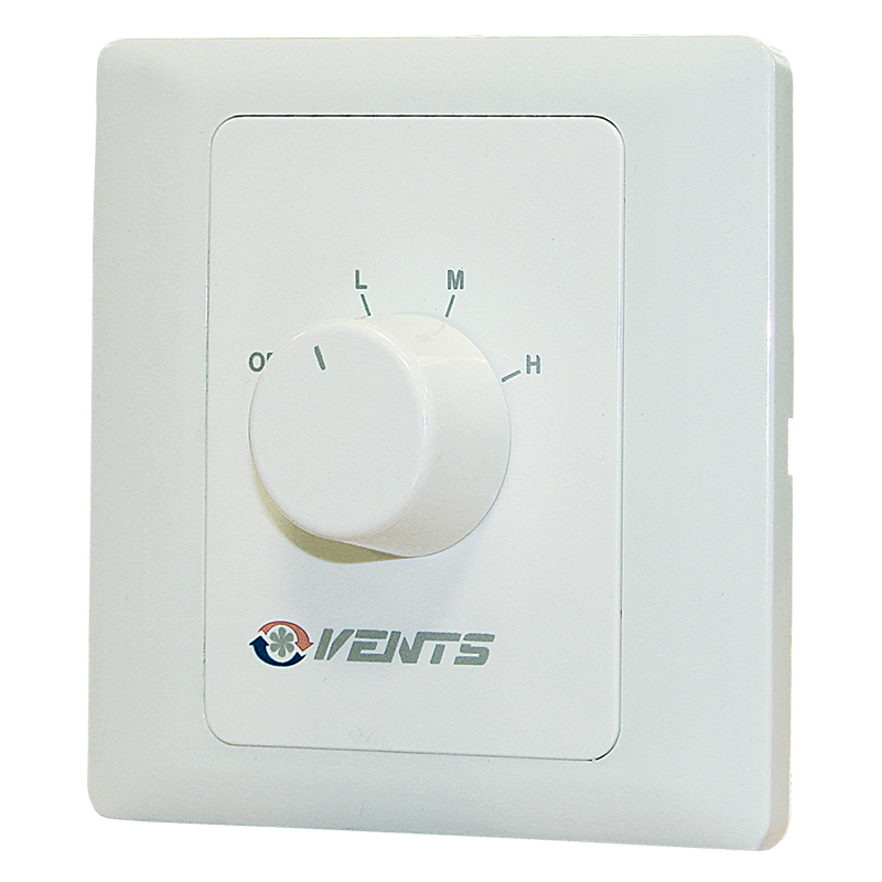
| CONTROL | |
|
|
| MOUNTING EXAMPLE | |
 |
|
|
|
- Selection method:
- Air flow:
- Pressure:
- Air flow: --
- Pressure: ---

Mark of conformity to the European Quality Standards and Electrical Safety issued by Association for Technical Inspection (Technischer Überwachungsverein, Germany).

CE mark means that the equipment is produced in compliance with the quality and safety standards provided by EU regulations for the given product type (marked by manufacturer).

Mark of conformity to the Polish Quality Standards and electrical safety issued by PCBC (Polish center for testing and certification).

Mark of conformity to the Slovak Quality Standards and electrical safety issued by EVPU (Slovakia).

Mark of conformity to the Ukrainian Quality Standards and electrical safety issued by UkrTEST.

Mark of conformity of the goods subject to obligatory certification in DSTR system as well as technical norms and standards acting in Russian Federation. Confirmed by the RosTEST certificates (Moscow).

Insulation class: double insulation.

Equipment protection rating.

Applicance protection class.

Equipment protection rating.

Equipment protection rating.
 RoHS (Restriction of Hazardous Substances Directive) is the directive on the restriction of the use of certain hazardous substances, was adopted in February 2003 by the European Union.
Equipment protection rating.

Equipment protection rating.

Equipment protection rating.
| Name | Description |
| T timer modification |
The fan is switched on to the maximum speed manually with the external switch, turn-on delay time is 50 seconds. The return to default position is performed with the timer, run-out time is 6 minutes. Continuous low speed operation is possible. |
| TR adjustable timer modification |
The fan can be switched to the maximum speed manually with the external switch. Turn-on delay time is set with the internal regulator ranging from 0 to 150 seconds. Run-out time is set with the internal regulator from 2 to 30 minutes. Continuous low speed operation is possible. |
| I interval switch modification |
The fan switches periodically to the maximum speed while operation. The switching interval is set by means of the internal regulator ranging between 0.5 and 15 hours. Run-out time is 10 minutes. The fan can be switched manually with the external switch, turn-on delay time is 50 seconds. Continuous low speed operation is possible. |
| H humidity sensor modification |
The fan switches to the maximum speed as relative humidity level in the room increases. It switches off as relative humidity level drops by 10 % below the set level. The humidity threshold is adjusted in the range between 60 % and 90 %. Force switching to the maximum speed is provided, in this case the turn-on delay time is 50 seconds, and the run-out time is set by the internal regulator between 2 and 30 minutes. Continuous low speed operation is possible. |