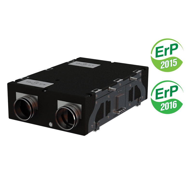
VENTS VUE 180 P5
Heat recovery air handling unit in sound- and heat-insulated casings. Air flow up to 220 m³/h. Heat recovery efficiency up to 94 %.
- Description
- Characteristics
- Capacity diagram
- Downloads
- Dimensions
- Additional characteristics
- Designation key
- Accessories
Description
Description
| DESCRIPTION | |||||
|
|
||||
| FILTER | CASING | ||||
|
|
||||
| FANS | |||||
|
|
||||
| HEAT EXCHANGER | |||||
|
|
||||
| CONTROL AND AUTOMATION | |||||
|
|
||||
| FREEZE PROTECTION | INSTALLATION | ||||
|
|
||||
| UNIT DESIGN | |||||
 |
|||||
| APPLICATION OPTIONS | |||||
 |
|||||
Characteristics
Characteristics
| Parameter |
VUE 180 P5 |
Measurement unit |
|---|---|---|
| Phase | 1 | ˜ |
| Voltage | 230 | V |
| Maximum unit power | 117 | W |
| Maximum unit current | 0.54 | A |
| Frequency | 50/60 | Hz |
| Air capacity | 220 | m³/h |
| RPM | 2317 | min-1 |
| Heat recovery efficiency | 79...94 | % |
| Transported air temperature | -25 ... +60 | °С |
| Sound pressure level at 3 m distance | 35 | dBА |
| Casing material | expanded polypropylene | - |
| Insulation | EPP 30-15 mm | - |
| Filter: extract | G4 | - |
| Filter: supply | G4 (F7*) | - |
| Connected air duct size | 150 | mm |
| Weight | 14 | kg |
| Heat exchanger material | enthalpy | - |
| Heat exchanger type | counter-flow | - |
| SEC Class | D | - |
Capacity diagram
Capacity diagram
- Selection method:
- Air flow:
- Pressure:
Operating point
- Air flow: --
- Pressure: ---
Files archieve
Downloads
Select document type
Dimensions
Characteristics

| Parameter | Value | Measurement unit |
|---|---|---|
| ∅D | 150 | mm |
| B | 600 | mm |
| B2 | 326 | mm |
| H | 264 | mm |
| L | 900 | mm |
Additional characteristics
Additional characteristics
| A-weighted sound power level | Total | Octave frequency band [Hz] | LpA, 3 m dBA | LpA, 1 m dBA | ||||||||
| dBA | 63 | 125 | 250 | 500 | 1000 | 2000 | 4000 | 8000 | ||||
| LwA to supply air inlet | dBA | 59 | 27 | 46 | 54 | 55 | 53 | 48 | 44 | 35 | ||
| LwA to supply air outlet | dBA | 60 | 27 | 46 | 54 | 55 | 52 | 49 | 44 | 35 | ||
| LwA to supply air outlet | dBA | 55 | 25 | 41 | 50 | 51 | 44 | 42 | 39 | 30 | ||
| LwA to exhaust air outlet | dBA | 55 | 26 | 41 | 51 | 51 | 44 | 42 | 39 | 31 | ||
| LwA to environment | dBA | 54 | 18 | 36 | 47 | 49 | 48 | 43 | 37 | 33 | 33 | 43 |
Calculation of air temperature downstream of the heat exchanger:
t = toutd + khr * (textr - toutd) / 100,
where
toutd – outdoor air temperature °С
textr – extract air temperature °С
khr – heat exchanger efficiency (according to the diagram) [%]
Designation key
Designation key
Accessories
Accessories
| Model | G4 panel supply filter | F7 panel supply filter |
 |
 |
|
| VUT 180 P5 | SF 214 x 186 х 18 G4 | SF 214 x 186 x 48 F7 |
| VUE 180 P5 |


 Domestic fans
  Industrial and commercial fans
  Single-room ventilation systems with heat recovery
  Air handling units
  Air heating systems
  Smoke extraction and ventilation
  Air sterilizers
  Accessories for ventilating systems
  Electrical accessories
  Ventilation ducts and fittings
  Air distribution components
  Ventilation kits and vents


